Tuesday, October 27, 2015

Success and a Mystery

I have finally been able to finish cutting through the shaft on my Minn kota Traxxis 80 trolling motor. This brings me one step closer to putting it into my 1910 power dory. The original motor was a low hp make and break gas motor—now we will be going electric.  Here are some pics;
 First attempt at cutting the shaft.  The tubing cutter did not have enough depth.  Needed a pipe cutter which I finally found at Essex Rental.  When I told the counterman what I was doing, he got the cutter and we went out to the truck and finished the cut—no charge. Thanks.
 Here is the finished product.  Now I need to bore a hole through for the clamp.  Should be a piece of cake.  Please notice the brown wire.  That is the mystery.  Why is it there?  What does it do?  The insulation has not been stripped, there is no connector on the end as they other two wires have.
 A closeup of the three wires above. I will neaten up the cut, but there are no rough edges, seems to be some sort of carbon fibre.  And, below, the motor in place with a temporary spacer.  I am counting on the bottom of the hull to act as a doelfin.  Waiting patiently for an answer from Minn kota on the brown wire.

Thursday, October 22, 2015

Motor in Place (More or Less)

I have dry fit the motor into the tubular motor well and mocked up a skeg and guard.  Here are some pics including the ones I thought were lost yesterday.  The digital world is a mystery to this old carpenter.
 Here is the mostly apart head just before i was able to remove the control panel's last two screws.
 And now all is apart.  The blue knob unit is the speed control, forward and reverse.
 And here is what will get inserted up through the motor well.
 A view of the skeg mockup from the bow
 And a bit closer.  The white collar is a bit I had to cut off one of the thru hulls and now am using it as a temporary spacer. Will try to find something better before we are finished.
 This is a close up showing the cutout in the skeg (2 x 12 x 54 inch white oak) the trailing edges of which will be feathered to eliminate turbulence on the prop.  The top projection on the skeg is to add support to the metal (now in the form of a piece of tubing) protection of the prop and motor.  I am considering bringing the metal down in front of the prop, almost vertical to give it more strength. Can you picture it?  I want to use 3/4 black iron pipe for the metal guard, maybe have it let into the top of the skeg and terminating in a threaded plate (can't remember the correct name) on the flat in fromt of the prop.  The pic does not show it well but there is plenty of room. I realize I should have put something while behind the motor to make it all more clear.  Click on the pics to enlarge.

Wednesday, October 21, 2015

All Stripped

Well, this never happened before, lost a whole slew of pics of the dismantling.  There was a collar around the shaft that came off nicely, set that aside and took out the two screws I could find for the main control panel, then found two more.  There two would be the last to be removed and they did not want to come out, probably the heads were buggered when installed.  I was about to drill them out when I gave it one more try and got them both out.  I had pictures of all of this, please feel free to use your imagination. 

Removing the control panel I was able to thread the two wires, on the left of the pic above, out and slide off the mounting bracket and now I have just a shaft and lower unit with no other accouterment. 

Tomorrow I will flip the hull, dry fit the tubular motor well and insert the shaft to see where it should be cut.  At the same time I will be able to get an idea of what I will need for a skeg and other protection for the lower unit.

Tearing Apart the Traxxis

The living room floor has become the operating room, mainly because the shop is littered and full of other projects. Dropping a screw on the floor out there would make finding it the literal needle in a haystack,  Here are some pics beginning with the last time we will see Traxxis as a whole.
 The next two show the wonderful articulation of the tiller which sadly we will forgo in the interest of maintaining the illusion that this old boat has not been modernized.

 Here is the tubular motor well and the next shows the detail of the lower assembly with the full thread thru hull, a necessity since the threads need to be longer to fit into the plumbing adapter.
 A closeup
 Aaarrggh, the pristine, brand new motor is being torn asunder
 There were six screws to get the top off revealing the underside of the battery tester.  I am hoping to be able to mount this somewhere in the boat when all is said and done.
 and six more to take the tiller apart, fortunately all the same!
 Tiller apart
 and speed control knob (in blue) removed from tiller arm.

 A shot directly into the control panel.  I have tried removing the heavy battery wires from the panel but guess I need to go out to the shop and get some pliers, but before I do I wanted to post this much.  While at the computer I got on the WB index and found the article on stick steering.  Not sure there is enough detail there but I need to read further.

Saturday, October 17, 2015

The Tubular Motor Well Assembled

 Above is a reminder of what we are shooting for (click on photos to enlarge) I am thinking of using 1 inch pipe for the metal part of the motor protection rather tun flat stock.  The prop measures around 11 inches so the skeg will be pretty large.
 A thru hull with wedges to allow well to be vertical
 Motor well dry fit using new full thread thru hull, the one above did not have enough threads to allow the adapter to be threaded on.
 The motor well will be affixed to the thwarts.  The afterdeck will have a hatch to make all of that nice space available for storage.  New deck beam to the right was needed as decking is only `/2 inch spruce.
 Pictured below is a closeup of the thru hull/wedge combo.  When it is permanently installed there will be bedding and thread tape to hopefully give a water tight seal.

 Below shows the original electric switch.  I have not tested it to be sure it functions but if it does it will do nicely for the nav lights.  Trying to decide if the control head should simply stick up above the afterdeck.  I would function beautifully but clash with the beauty of the old boat.  What to do.  I could also shorten the tube, cut a slot in the thwart for the handle to stick out of and hide most of the modern stuff while maintaining the convenience of one handed control.  It may be easier to decide once the motor arrives on Tuesday.
 And, here is a shot of the power prop.  The motor comes with the weedless variety as part of the package so I will have a spare of sorts.

Sunday, October 11, 2015

Working on Motor Well Design

So many good ideas.  Kick up rudder mount, transom mount, tube style motor well with skeg?  Which would serve best?  Which would make the least impact on a future  restoration allowing for the installation of the original one lung hit and miss banger?  I am leaning strongly towards the skeg and tube option. A steel bar would complete the protection of the motor. It would need to be removable for the installation of the motor.  No problem there.  Here is a sketch—click on it to enlarge.
Not very pretty, but fairly in scale. The steel would run up the transom and onto the skeg enough to be bolted in place.  Since the skeg will be of 1 1/2 spruce, I suppose the steel could be the same width by one quarter? The thru hull threads fit nicely into a threaded 1 1/2 inch PVC coupling which in turn accepts the 1 1/2 inch pipe. There would be the same thru hull/PVC arrangement at the top of the pipe as well.  The top of the unit will be supported by a thwart of some sort.  Altogether makes a fairly good support at top and bottom for the shaft.  Not sure how the steering will be accomplished but should not be too much of a problem.

Saturday, October 10, 2015

Motor Well? Where? How? Skeg?

Here we are at a crossroads.  The hull has been stripped, new bottom installed and glassed to the top of the garboard.  All bare wood given two coats of CPES. All has been sanded, but what to do about the motor well?  Here are some recent pics in no special order.
 Filled in the missing piece pf 1/2 inch ply and glassed.
 The glassed bottom and garboard have second and third fill coat
 Top two strakes have been coated with two coats of CPES

 All has been sanded smooth and ready for paint.  Problem?  What to do for a motor well?

 More pics than I need but very please with how she looks, knots and all

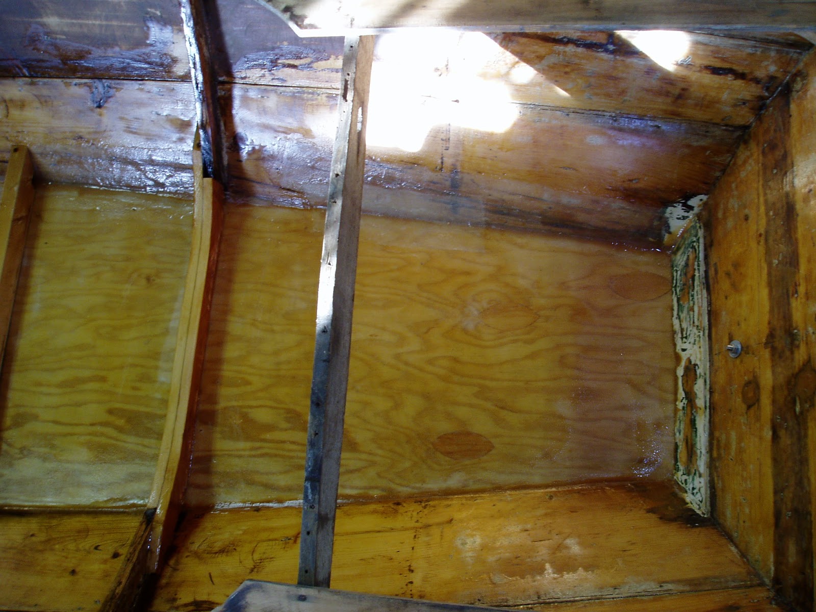
 Several pics of the aft end where a motor well might be installed.  I have acquired two 1 1/2 inch through hulls and a length of 1 1/2 PVC that altogether make a fine motor well if that is the route I go.  Problem? Having the motor in that vulnerable position makes it necessary to have a skeg to protect the motor from underwater obstacles.  A full motor well, say 10 inches wide and 30 inches long would allow the motor to kick up and eliminate the need for a skeg, or at least allow for a minimal one for directional stability.

 More pics of the area in question.  The bottom is only 18 inches wide where it meets the transom.

 Looking aft, the tubular motor well would be just behind the support for the aft deck
 The tubular motor well would not addd any drag to the hull, but I fear the full on motor well might, or might not make enough drag to worry about.  Thoughts?
 If I go a full on motor well it might go in front of the deck support and it would allow for the well to be  long enough to allow the motor to kick up into the boat.  I really do not want to cut into the transom.
 Here is my tape showing the distance from the transom to the first (last?) frame. I would really appreciate any thoughts on the location of and type of motor well.